
Products
Comprehensive electrical corrosion prevention systems
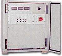
Potentiostatic Power Supply Units
Potentiostatic Power Supply Unit 2045
Features:
- Different output voltage and current ranges up to 24V 10A / 12V 20A per circuit
- 1 to 4 anode circuits can be added in a 640x600x400 (HxWxD) enclosure or 1 to 10 anode circuits obtained using 1600x600x600 cabinet
- 3 different reference electrode input ranges
- Potentiostatic or constant current mode selection on each module
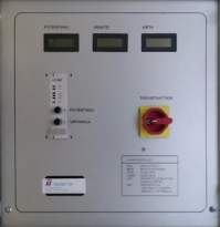
- LCD panel meters for electrode potential, output voltage and output current
- Potential and current limit adjustments for every circuit
- Clear LED monitoring of operation on each module:
- PWR for power on
- MEAS blinks when LCDs monitor this module
- OVER for overprotection
- UNDER for under protection
- LIMIT for indicating current limit operation
- MAN for indicating constant current mode
- Optionally, the under protection can be monitored remotely by an alarm contact. The alarm contact can be either combined for all the circuits or used separately.
- Another monitoring option for potential, current and voltage is as a 4…20mA signal
- RS485/MODBUS digital field bus connection available for full control and monitoring for all of the circuits
Technical Specifications
Mains input:
3 x 400VAC 50Hz 10A ±10% tai 1 x 230VAC 50Hz 10A ±
10%, Muita jännitteitä pyynnöstä
Output ranges:
12V 10A – 24V 5A
12V 20A – 24V 10A
all anode circuits must have same
output current and voltage
Output ripple:
< 50mV
Reference electrode input ranges:
-250…+750mV, e.g. Zn – Fe
-2000…0mV, e.g. Ag/AgCl2 – Al
Cu/CuSO4 – Fe
-450…0mV
jumper setting for input range on control unit
Input impedance:
1MΩ,
Operating temperature:
-10 … +40°C
on request: -30 … +40°C
Protection class:
IP44
Dimensions:
1-4 anode circuits: 640x600x400 (HxWxD)
1-10 anode circuits: 1600x600x600
EMC:
EN 50081-1 (1992) emissions
EN 50082-2 (1995) immunity
(FIMKO)
Approvals: CE
ASCP-0.75/1.5 and ASCPSW-0.5/1.0
3045
Automatic Supply of Cathodic Protection Potentiostatic Power Supply Units ASCP-0.75/1.5 and ASCPSW-0.5/1.0
4 models:
- ASCP-0.75, Tulo: 42V 15A,
thyristor controlled - ASCP-1.5, Tulo: 42V 30A,
thyristor controlled - ASCPSW-0.5, Tulo: 42V 10A / 21V
20A, switch mode - ASCPSW-1.0, Tulo: 42V 20A / 21V
40A, switch mode
Features:
- Designed mainly for water and natural gas pipelines and other underground structures but can be used in other locations as well.
myös muihin maanalaisiin rakenteisiin,
mutta voidaan käyttää myös muissa kohteissa - Housed in a 500x500x300 enclosure
- Efficient protection against lightning at input, output and power input (model -O)
- 3 different reference electrode input ranges
- Potentiostatic or constant current mode selection
- LCD panel meters for electrode potential, output voltage and output current
- Potential and current limit adjustments for every circuit
- Clear LED monitoring of operation on each module:
- PWR for power on
- MEAS blinks when LCDs monitor this module
- OVER for overprotection
- UNDER for under protection
- LIMIT for indicating current limit operation
- MAN for indicating constant current mode
- Option for monitoring the under protection remotely
- Option for monitoring the potential from a 4…20mA signal
- Releohjatut virtalähteet on saatavillamyös 48VDC sisääntulolla.
Technical Specifications
Mains input:
230VAC 50/60Hz 16A ±10%
Other voltages on request
48VDC input available for switch mode models
Output ranges:
ASCP-0.75 42V 15A
ASCP-1.5: 42V 30A
ASCP-0.5: 42V 10A / 21V 20A
ASCP-1.0: 42V 20A / 21V 40A
Output ripple:
models 0.75 and 1.5: a few volts at maximum load
models 0.5 and 1.0: < 500mV
Reference electrode input ranges:
-250…+750mV, e.g. Zn – Fe
-2500…0mV, e.g. Ag/AgCl2 – AlCu/CuSO4 – Fe
-3000…0mV
jumper setting for input range on control unit
Input impedance:
1MΩ,
Operating principle:
Models 0.75 and 1.5:
Thyristor phase angle controlled bridge
rectifier controlled by potentiostatic feedback loop
Models 0.5 and 1.0:
DC/DC switch mode converter module controlled by potentiostatic feedback loop.
Loop response is selected by dip switches on control unit
Operating temperature:
-10 … +50°C
on request: -30 … +50°C (models -E)
Protection class: IP44
500x500x300 (HxWxD)
EMC:
Models 0.75 and 1.5:
EN 50081-1 (1992) emissions
EN 50082-2 (1995) immunity
(FIMKO)
Surge immunity:
Models 0.75 and 1.5:
EN 61000-4-5 ja
4kV test to all inputs and outputs
Approvals: Models 0.75 and 1.5: CE
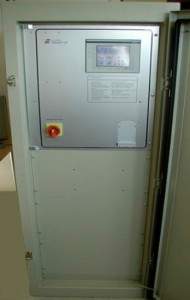
3045
3045PLC power supply unit
Features:
- All supervisions and adjustments can be made directly from a user friendly touch screen color terminal
- up to 30 anode circuits using either 1600x600x500 or 760 x 600 x 350 cabinet, size depends upon required power
- Both analog gauges and digital view for potential, output voltage and current
- Current limit and the potential value can be controlled either by control knobs or numerically from the screen.
- Possibility to add a customer specific display to show a general view of the CP system including real time potential levels in different areas.
- Potentiostatic or constant current mode selection for each circuit.
- Several reference electrode inputs for each circuit.
- Different output voltage and current ranges according to customer specifications.
- Alarm relay, modem, RS485/MODBUS-slave and WEB-server options for external monitoring.
WEB server option includes:
- Same supervision and adjustment screen as in touch screen panel accessible by standard web browsers.
- Can be connected to customer intranet or public internet for remote control
- Point to point connection is also possible from your office by a GSM modem
- Historic view for taking look at potential and current trends

Products in pdf-format:
Al-anodes
Aluminium Hull Anodes
| Aluminium Hull Anodes | ||||||
|---|---|---|---|---|---|---|
| Type | Material | Alumin weight (kg) | Anode weight (kg) | L (mm | B (mm) | H (mm) |
| 15AL | Aluminium | 1,1 | 1,5 | 220 | 100 | 30 |
| 25AL | Aluminium | 2 | 2,5 | 270 | 120 | 32 |
| 43AL | Aluminium | 3,4 | 4,3 | 370 | 120 | 32 |
| 60AL | Aluminium | 5,2 | 6 | 600 | 120 | 41 |
| 80AL | Aluminium | 7,5 | 8 | 350 | 150 | 62 |
| 90AL | Aluminium | 7,8 | 9 | 960 | 120 | 37 |
| 93AL | Aluminium | 7,9 | 9,3 | 960 | 120 | 37 |
| 114AL | Aluminium | 10,6 | 11,4 | 60 0 |
120 | 76 |
| 170AL | Aluminium | 15,8 | 17 | 960 | 120 | 73 |
| 175AL | Aluminium | 16,1 | 17,5 | 960 | 120 | 73 |
| 350AL | Aluminium | 31,6 | 35 | 1920 | 120 | 71 |
| 399AL | Aluminium | 33,3 | 39,9 | 2500 | 105 | 60 |
Standard Aluminium Anodes – Static Structures
| Standard Aluminium Anodes – Static Structures | ||||||
|---|---|---|---|---|---|---|
| Type | Material | Alumin weight (kg) | Anode weight (kg) | L (mm) | B (mm) | H (mm) |
| 280 HAL | Aluminium | 21,5 | 27,3 | 1000 | 112 | 90 |
| 385 HAL | Aluminium | 30 | 37,7 | 1400 | 112 | 90 |
| 516 HAL | Aluminium | 40 | 51,6 | 2015 | 110 | 85 |
| 485 HAL | Aluminium | 40 | 47,7 | 1440 | 130 | 105 |
| 527 HAL | Aluminium | 45 | 52,7 | 1525 | 133 | 104 |
| 566 HAL | Aluminium | 45 | 56,6 | 2250 | 110 | 85 |
| 616 HAL | Aluminium | 50 | 61,6 | 2480 | 110 | 85 |
| 585 HAL | Aluminium | 50 | 58,5 | 1500 | 140 | 110 |
| 625 HAL | Aluminium | 54,8 | 62,5 | 1500 | 140 | 120 |
HAL-tyypin anodeja on pyynnöstä saatavilla 2.5m pituuteen asti. Mitat ja painot ovat nimellisarvoja.
Standard Aluminium Anodes – Tank Anodes
| Standard Aluminium Anodes – Tank Anodes | ||||||
|---|---|---|---|---|---|---|
| Type | Material | Alumin weight (kg) | Anode weight (kg) | L (mm) | B (mm) | H (mm) |
| 44TAL | Aluminium | 3,8 | 4,4 | 400 | 70 | 60 |
| 68TAL C4 | Aluminium | 5,2 | 6,8 | 700 | 60 | 50 |
| 68TAL C3 | Aluminium | 5,2 | 6,8 | 700 | 60 | 50 |
| 96TAL | Aluminium | 8,5 | 9,6 | 750 | 77 | 65 |
| 105TAL | Aluminium | 8,7 | 10,3 | 1235 | 64 | 51 |
| 100TAL | Aluminium | 8,7 | 10 | 1235 | 62 | 45 |
| 107TAL C4 | Aluminium | 9,1 | 10,7 | 750 | 77 | 65 |
| 107TAL C3 | Aluminium | 9,1 | 10,7 | 750 | 77 | 65 |
| 125TAL | Aluminium | 11,2 | 12,5 | 1235 | 68 | 57 |
| 130TAL | Aluminium | 11,2 | 12,8 | 1235 | 68 | 58 |
| 160TAL | Aluminium | 13,7 | 15,7 | 1600 | 70 | 52 |
| 200TAL | Aluminium | 17,7 | 19,7 | 1600 | 76 | 63 |
| 200TAL | Aluminium | 18,4 | 20 | 1600 | 76 | 63 |
| 230TAL | Aluminium | 20 | 22,6 | 2100 | 74 | 56 |
| 320TAL | Aluminium | 29,7 | 31,7 | 1600 | 95 | 84 |
Muita anodityyppejä on mahdollista valmistaa asiakkaan vaatimusten mukaisesti. Kaikki mitat ja painot ovat nimellisarvoja.
General properties of AI-anodes
Chemical composition
Bacalin alloy
Zn 3,5 – 5,5%
In 0.01 – 0.03%
Mn 0,1 – 0.25%
Fe 0,22% maks.
Si 0,10% max.
Cu 0,01% maks.
Al Loput
Electrochemical properties:
Closed circuit potential:
-1120mV vs Ag/AgCl
Current capacity::
max. 2550 Ah/kg
Tehollisarvo: 86%
Consumption:
3.5 kgs per Ampere/Year
Special advantages:
High driving voltage, very suitable in applications where water resistivity limits the use of standard aluminium alloy.
Zn-anodes
Standard Zinc Shaft Anodes OD/ID
| Standard Zinc Shaft Anodes OD/ID | ||||
|---|---|---|---|---|
| Type 1 | Material | Zinc weight (kg) | Anode weight (kg) | A (mm) |
| 44/25 | Zinc | 0,165 | 0,1 | 44 |
| 44/22 | Zinc | 0,185 | 0,1 | 44 |
| 49/30 | Zinc | 0,2 | 0,2 | 49 |
| 44/19 | Zinc | 0,2 | 0,2 | 44 |
| Type 2 | Material | Zinc weight (kg) | Anode weight (kg) | A (mm) |
| 55/30 | Zinc | 0,685 | 0,6 | 55 |
| 55/22 | Zinc | 0,83 | 0,8 | 55 |
| 55/19 | Zinc | 0,86 | 0,8 | 55 |
| 70/40 | Zinc | 1,07 | 1 | 70 |
| 70/38 | Zinc | 1,1 | 1,1 | 70 |
| 70/35 | Zinc | 1,23 | 1,2 | 70 |
| 70/32 | Zinc | 1,3 | 1,3 | 70 |
| 85/60 | Zinc | 1,85 | 1,8 | 85 |
| 85/50 | Zinc | 2,37 | 2,3 | 85 |
| 85/45 | Zinc | 2,65 | 2,6 | 85 |
Standard Zinc Hull Anodes
| Standard Zinc Hull Anodes | ||||||
|---|---|---|---|---|---|---|
| Type | Material | Zinc weight (kg) | Anode weight (kg) | A (mm) | B (mm) | H (mm) |
| Bera 50 T | Zinc | 4,4 | 5 | 47 | 40 | |
| Bera 105 T | Zinc | 9,4 | 10 | 70 | 60 | |
| Bera 140 T | Zinc | 12,6 | 14 | 1235 | 40 | 40 |
| 220 T | Zinc | 20,2 | 22 | 64 | 51 | |
| Bera 225 T | Zinc | 20,3 | 22,5 | 1235 | 50 | 50 |
| 300 T | Zinc | 28,2 | 30 | 68 | 58 | |
| Bera 305 T | Zinc | 28,3 | 30,5 | 1235 | 58 | 58 |
| 450 T | Zinc | 42,7 | 45 | 76 | 63 | |
| 500 T | Zinc | 48,1 | 50 | 78 | 68 | |
| 570 T | Zinc | 55 | 57 | 86 | 66 | |

Standard Zinc Shaft Anodes OD/ID
| Standard Zinc Shaft Anodes OD/ID | ||||||
|---|---|---|---|---|---|---|
| Type | Material | Zinc weight (kg) | Anodin paino(kg) | A (mm) | B (mm) | H (mm) |
| Bera 2 | Zinc | 0,21 | 0,2 | 98 | 35 | 15 |
| Bera 5 | Zinc | 0,44 | 0,5 | 120 | 46 | 23 |
| Bera 10 | Zinc | 0,9 | 1 | 140 | 62 | 28 |
| Bera 20 | Zinc | 1,9 | 2 | 165 | 90 | 30 |
| Bera 22 | Zinc | 2,1 | 2,2 | 230 | 77 | 32 |
| Bera 35 | Zinc | 3,2 | 3,5 | 220 | 100 | 29 |
| Bera 55 | Zinc | 5,1 | 5,5 | 260 | 110 | 32 |
| Bera 102 | Zinc | 9,3 | 10,2 | 350 | 150 | 32 |
| Bera 105 | Zinc | 9,6 | 10,5 | 405 | 220 | 35 |
| Bera 145 | Zinc | 13,5 | 14,5 | 405 | 220 | 45 |
| Bera 155 | Zinc | 14,7 | 15,5 | 590 | 120 | 45 |
| Bera 235 | Zinc | 21,5 | 23,5 | 960 | 120 | 39 |
Standard Zinc Tank Anodes
Shame With Ø 5 mm, 1/4”, 3/8” or 1/2″ core or without core
| Standard Zinc Anones for Cooling Systems | |||
|---|---|---|---|
| Type | Anode weight (kg) | Diam (mm) | L (mm) |
| 12 K/33 | 0,03 | 12 | 33 |
| 12 K/90 | 0,03 | 0,07 | 90 |
| 12 K/300 | 0,25 | 12 | 300 |
| 13 K | 0,05 | 13 | 56 |
| 17 K300 | 0,5 | 17 | 300 |
| 22 K200 | 0,5 | 22 | 200 |
| 28 K400 | 1,7 | 28 | 400 |
| 30 K320 | 1,6 | 30 | 320 |
| 40 K215 | 2 | 40 | 215 |
| 50 K215 | 2,9 | 50 | 215 |
| 60 K215 | 4,5 | 60 | 215 |
| 70 K215 | 5,8 | 70 | 215 |
| 80 K215 | 7,5 | 80 | 215 |
| 104 K27 | 1,6 | 104 | 27 |
| Type | Anode weight (kg) | Diam (mm) | H (mm) | L (mm) | B (mm) |
| 78 K | 1,2 | 78 | 45 | ||
| 140 K | 2,5 | 140 | 25 | ||
| 180 K | 4,2 | 180 | 25 | ||
| 200 K | 5,1 | 200 | 25 | ||
| KBS 1 | 1,5 | 20 | 240 | 45 | |
| KBS 2 | 2 | 15 | 190 | 100 | |
| KBS 3 | 7,1 | 30 | 220 | 150 | |
| KBS 4 | 7 | 34 | 220 | 130 | |
| KBS 5 | 0,9 | 15 | 170 | 50 | |
| KBS 6 | 0,3 | 12 | 120 | 50 |
General properties of the Zn-anodes
Chemical composition
BERA zinc alloy
Al 0,15 – 0,30%
Cd 0,04 – 0,06%
Fe 0,002% max.
Sn 0,001% max
Cu 0,001% max.
Pb 0,004% max.
Si 0,10% max.
Zn remainder
Electrochemical properties:
Efficiency 95%
Potential -1,10 V, Cu/CuSo4 ref.
Capacity 780 Ampere hours per kg
Consumption 11.2 kgs per ampere year